VLAN Configuration Using Cisco Packet Tracer

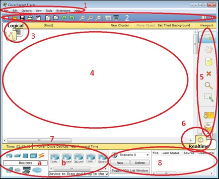
Creating a simple topology using packet tracer

Creating VLAN

Initial topology for the practice of VLAN, VTP, DTP and Router on Stick

SWITCH1

S1(config)#vlan 10
S1(config-vlan)#exit
S1(config)#vlan 20
S1(config-vlan)#exit
S1(config)#

Assigning VLAN Membership

switch1

S1(config)#interface fastEthernet 0/1
S1(config-if)#switchport access vlan 10
S1(config-if)#interface fastEthernet 0/2
S1(config-if)#switchport access vlan 20

switch2

S2(config)#interface fastEthernet 0/1
S2(config-if)#switchport access vlan 10
S2(config-if)#interface fastEthernet 0/2
S2(config-if)#switchport access vlan 20

switch3

S3(config)#interface fastEthernet 0/1
S3(config-if)#switchport access vlan 10
S3(config-if)#interface fastEthernet 0/2
S3(config-if)#switchport access vlan 20

Testing VLAN configuration

1] Access PC’s command prompt to test VLAN configuration. Double click PC-PT and click Command Prompt

A] VLAN10

VLAN Test

B] VLAN20

Test VLAN

Configure Router

Access command prompt of Router

To configure Router on Stick we have to access CLI prompt of Router. Click Router and Click CLI from menu items and Press Enter key to access the CLI

Run following commands in same sequence to configure Router

Router>enable
Router#configure terminal
Enter configuration commands, one per line.  End with CNTL/Z.
Router(config)#interface fastEthernet 0/0
Router(config-if)#no ip address
Router(config-if)#no shutdown
Router(config-if)#exit
Router(config)#interface fastEthernet 0/0.10
Router(config-subif)#encapsulation dot1Q 10
Router(config-subif)#ip address 10.0.0.1 255.0.0.0
Router(config-subif)#exit
Router(config)#interface fastEthernet 0/0.20
Router(config-subif)#encapsulation dot1Q 20
Router(config-subif)#ip address 20.0.0.1 255.0.0.0
Router(config-subif)#exit


Network Devices

Cisco devices and Packet Tracer devices

Selecting Switches or Routers from the device-type selection box lists both Cisco devices and some devices labeled Generic. These are custom Packet Tracer devices running on Cisco IOS, but the slots that hold the modules are different.

Routers

A router provides connectivity between two logical networks. Every router in Packet Tracer can be switched on or off by using the provided power button.

The power switch is required to make a device simulate its real counterpart. Modules can be added or removed only after powering off the device. If the running configuration is not saved, power cycling a device will make it lose its configuration.

The following routers are available in Packet Tracer:

  • Cisco 1841: This is an Integrated Service Router (ISR) having two Fast Ethernet ports, two slots for High Speed WAN Interface Cards (HWICs), and one slot for Advanced Integration Module (AIM)
  • Cisco 1941: This is similar to the previous model but runs on Cisco IOS Version 15. It has two ports that operate at Gigabit Ethernet speeds.
  • Cisco 2620XM: This is a multiservice router with one Fast Ethernet port, two slots for WAN Interface cards, and one slot for AIM.
  • Cisco 2621XM: This is similar to the previous model, except that this router has two Fast Ethernet ports.
  • Cisco 2811: This ISR comes with two Fast Ethernet ports, four WIC slots, and a dual slot for AIM.
  • Cisco 2901: This router has two Gigabit Ethernet ports, four WIC slots, and two Digital Signal Processor (DSP) slots. This router uses Cisco  IOS Version 15.
  • Cisco 2911: This router has three Gigabit Ethernet ports and all the other features of the previous router. It runs on IOS Version 15.
  • Generic Router-PT: This is a custom router running on Cisco IOS. It contains 10 slots and has separate modules with a naming  convention beginning with PT.

    Switches

    A switch, also called a multiport bridge, connects more than two end devices together. Each switch port is a collision domain. The following switches are  available in Packet Tracer:

    • Cisco 2950-24: This managed switch comes with 24 Fast Ethernet ports.
    • Cisco 2950T-24: This switch is a member of the Catalyst 2590 Intelligent Switch family and has two Gigabit Ethernet ports in addition to the 24 Fast Ethernet ports.
    • Cisco 2960-24TT: This is another 24 port switch; the previous switch has Gigabit Interface Converter (GBIC) for Gigabit Ethernet ports,  whereas this switch has Small Form-factor Pluggable (SFP) modules  for the same. Note that this is a difference only on real switches,  it has no impact on Packet Tracer.
    • Cisco 3560-24PS: This switch is different from the others because it is a layer 3 switch that can be used to perform routing in addition to switching. The PS suffix implies support for Power over Ethernet (PoE), which can be used to power up IP phones without using power adapters.
    • Bridge PT: This is a device used to segment a network and it has only two ports (which is why it is a bridge; if it had more, it’d be called a switch).
    • Generic Switch PT: This is a Packet-Tracer-designed switch running on Cisco IOS. This is the only customizable switch with 10 slots and several modules.

Packet Tracer Network Simulator

Interface overview

The layout of Packet Tracer is divided into several components similar to a photo editor. Match the numbering in the following screenshot with the explanations given after it:

The components of the Packet Tracer interface are as follows:

  • Area 1: Menu bar – This is a common menu found in all software applications; it is used to open, save, print, change preferences, and so on.
  • Area 2: Main toolbar – This bar provides shortcut icons to menu options  that are commonly accessed, such as open, save, zoom, undo, and redo,  and on the right-hand side is an icon for entering network information  for the current network.
  • Area 3: Logical/Physical workspace tabs – These tabs allow you to toggle between the Logical and Physical work areas.
  • Area 4: Workspace – This is the area where topologies are created and simulations are displayed.
  • Area 5: Common tools bar – This toolbar provides controls for manipulating topologies, such as select, move layout, place note, delete, inspect, resize shape, and add simple/complex PDU.

Area 6: Realtime/Simulation tabs – These tabs are used to toggle between the real and simulation modes. Buttons are also provided to control the  time, and to capture the packets.

  • Area 7: Network component box – This component contains all of the network and end devices available with Packet Tracer, and is further  divided into two areas:

°     Area 7a: Device-type selection box – This area contains device categories

°     Area 7b: Device-specific selection box – When a device category  is selected, this selection box displays the different device models within that category

  • Area 8: User-created packet box – Users can create highly-customized packets to test their topology from this area, and the results are displayed  as a list.